Showing posts with label Electronic projects. Show all posts

Monday, 24 April 2017

Electric Power Steering conversion Phase 1

Today I'll share with you how I converted my power steering system to an electric power steering system on my AE102 corolla.

This is only a phase 1 as I want to implement variable PS assistance based on car speed. this would be covered in a second phase later on. This current system is in use on my daily driver since autumn 2016 and was used everyday in the canadian winter since then without failures.

Reasons for going on with this

  • totally disconnect the engine and PS system allowing for a more wild engine choice when space would not allow it otherwise, makes for easier future engine swaps. 
  • allows to turn off enterily the PS system for drag racing. giving an advantage vs regular driving. drops the rotating masses attached to the crankshaft and power losses.
  • allows you to enjoy a different steering sensitivity by the adjustment of a knob and find the spot where you feel best according to you particular car. allowing to take away the spongy steering feeling toyotas are know for.

Parts needed.

  • MR2 turbo electric PS pump motor and it's immediate hydraulic fittings.
  • custom bracket to hold the PS pump motor to the car.
  • PS fluid reservoir and low pressure hoses to reach PS pump motor
  • Hydraulic hose to join the PS pump motor and the steering rack.
  • 80a adjustable DC Motor controller. 
  • 80a fuse
  • 80a automotive relay 
  • 8ga wiring to reach car battery, fuse, relay and PS pump motor.
  • 18ga wiring to reach relay's coil and +b 
here is the DC motor controller I am using since last autum without issues. comes with it's tuning knob
e-bay 2000W PWM Motor Speed Control


Electrical wiring diagram.

no details are given on the PS pump motor wiring color yet


Pictures of the installation are yet to come when time allows.

Monday, 31 October 2016

Simplest Narrowband OX sensor simulator

BUILDING IT

 Hi, today I'll be sharing with you how to build a very simple narrowband oxygen sensor simulator, this thing is only useful to troubleshoot how an ECU reads the 2 states of an oxygen sensor. it does not simulate an oxygen sensor heater. On your left you will see the sensor curve for all NB oxygen sensors. the tool is simply a switch that outputs a ground path, or about 0.75 to 1V. allowing the user to simulate a rich or lean reading.


The Parts needed are very simple, and should be found at all local electronic parts shop.

4 X 1K resitors. 1/4w is fine
2 x 10k resistors. 1/4w is fine
3 x wires of different colors ,about 2 feet long gauge 20
1 x single pole double throw switch, something with 3 pins
2 x shrink wrap tubing for protecting the circuitry , or electrical tape

optional parts
shrink wrap to hide all of the 3 wires and the circuitry
3 x crocodile connectors
 Here you can see how I built it. very simple to do, twisting the resistors together and soldering it all in the end. adding the wires.
 complete tool ready for use

AND NOW PLAYING WITH IT

 I went ahead and proved the tool on my own like all mad scientist should be doing. Test subject is a 1997 toyota corolla, AE102 at birth , converted with an 92-93 3VZ-FE running a Canadian OBD1 A/T ECU with an OBD1READ device used in conjunction with TOYOBD1.


the tool sits on the front engine bank with the orange wire connected at the alternator pole, and the green wire connected to the chassis ground. white wire leads to the front bank ox sensor wire


First I warmed the engine up. then when ready ,toggling the switch with one hand an data logging in toyobd1 with the other I was able to fool my ECU into thinking the sensor reading was either rich or lean.

Summary

This tool can be used to make sure the wiring and  ECU are correctly working. leaving the only possible culprit to the sensor itself if something is wrong.

Saturday, 22 November 2014

Dirt cheap portable MAF sensing

A while ago I realized that a portable MAF sensor would be nice to have. That sensor can be useful to sense engine health or how well it can perform. The idea came to use a junkyard OBDII ECU who came equipped with a MAF sensor.


 An OBDII ECU?

Here are some advantages to go down this route
  • to get quantified readings from the sensors,no need to discover the OBDII sensors curves. You simply request a particular sensor reading. for instance what interest us today is the MAF sensor reading which returns a g/s flow rate.
  • It is easy to interface an OBDII ECU to a PC or cellphone.
  • It is easy to find a suitable ECU + matching MAF sensor in a junkyard for cheap
  • There is many software options to interface to OBDII ECUs.

As I am a Toyota fan I looked toward the Toyota 3.0L V6 ECU using MAF sensors, what was available in junkyards at that time was the 1995 Camry 1MZ-FE ecu, that MAF sensor can be installed inline which helps when installing, that particular MAF sensor should be able to read engine air flow from comparable power levels engine which is sufficient this time.

How do we get this brillant concept to life now?

I choose to use the OBDII ECU as a portable unit, lying on the car floor, running a long cable to the MAF on the engine, getting power through the cigarette lighter port.


You need to build a minimalist wiring harness for this ECU to work on your car. Remember that you want just 3 things, the OBDII ECU, it`s MAF, and an OBDII connector, it really is not that hard to do, something like 10 wires.

After you made sure your ECU is powered correctly and all needed wires are going to their rightful places it is time to get some data out of that setup. The good old ELM327 comes handy for this, you can buy BT OBD2 adapters, USB obd2 adapters, probably even RS232 obd2 adapters, there is also many software out there to read data from an OBD2 ECU that can be used to glance at the data.

What to do with it then?

What I want to do with my MAF sensor is to plot unknown flow curve of various VAF sensor from non OBDII engine, comparing readings from the OBD2 ECU through time vs those of the unit tested.

(Take note to never install a MAF behind something that could make turbulence such as a VAF, you will get erratic readings... MAF in front of VAF gives good results!, take also note that this is a temporary test setup  )

And now the resulting flow curve for the VAF sensor

Tuesday, 4 February 2014

Back to the future year 2009 : ST162 3S-GE with Honda P06 ecu

 Introduction

Like the title means, let's go back in the past, the year is 2009 , A time when Engine management systems were a mystery to me. At that time I started the project to get a 3S-GTE to work without having the matching ecu and much everything in fact. Back then my skills in electronics were not much better than installing car stereos and simple analog electronic stuff, fog lights,repair broken wires,nothing to fancy. Please excuse the poor presentation of subjects in the pictures, having known I would have shared them It would have looked better!
As the avaricious young Lad I was, I decided to go with the cheapest alternative in exchange for more required skills to succeed. I found on the web that Honda civic ECUs were modifiable quite easily and for cheap, I also found that they were successfully used on rare occasions on the 3S-GTE which was my ultimate goal, but first I wanted to make it work on a 3S-GE I had lying around, those engine share a lot EMS wise and would be less of a loss if something went real bad with the tuning. 
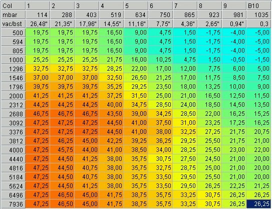
example igniton map
The leanring curve involved for a complete beginner was steep but I probably would do it the same way as the challenge was rewarding in the end. Please note that this document is a really rough tale of how to do this, 5 years have past since the events described here were made, so If you intend to do a similar project where to learn to work with those ECUs go to pgmfi.org, this is where I learned everything about the P06 and most of the basics surrounding Engine management systems and the common strategies used to modify pre-OBD2 oem ECUs. Please do your research too and do not rely solely on what is written here. Any questions asked will be replied to the best of my knowledge tough . For details on

Mecanical and electronical aspect
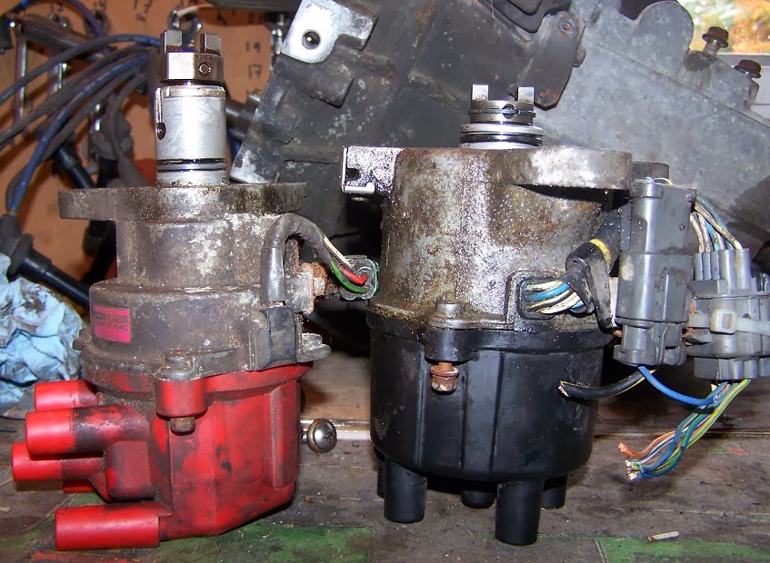
3S-GE left D15 right
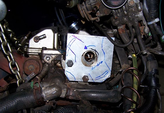
What was the biggest problem was that I neeeded to use the civic distributor( crank angle sensors are inside
) to match with the civic ecu. A friend of mine did the machining work to build an adaptor to bolt the distributor on the 3S-GE head and camshaft, Thanks Again Adam!.


The Honda P06 ecu was found in 1992-1995 d15 and d16 civic with already installed VTEC capabilities or not, was about 35-60 CDN$ available at most scrap yards.
Modifying cost were around 20-25 CDN$ in
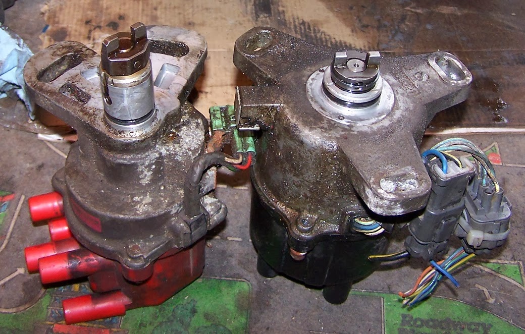
3S-GE left D15 right
parts. It required soldering inside the ECU and have the tools to burn EEPROM chips when necessary.

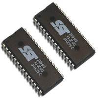
So at that time I bought tools to burn chips and a stock of 27C256 compatible EEPROMs,mine were SST27SF512, as time goes by findind compatible EEPROM is getting harder.

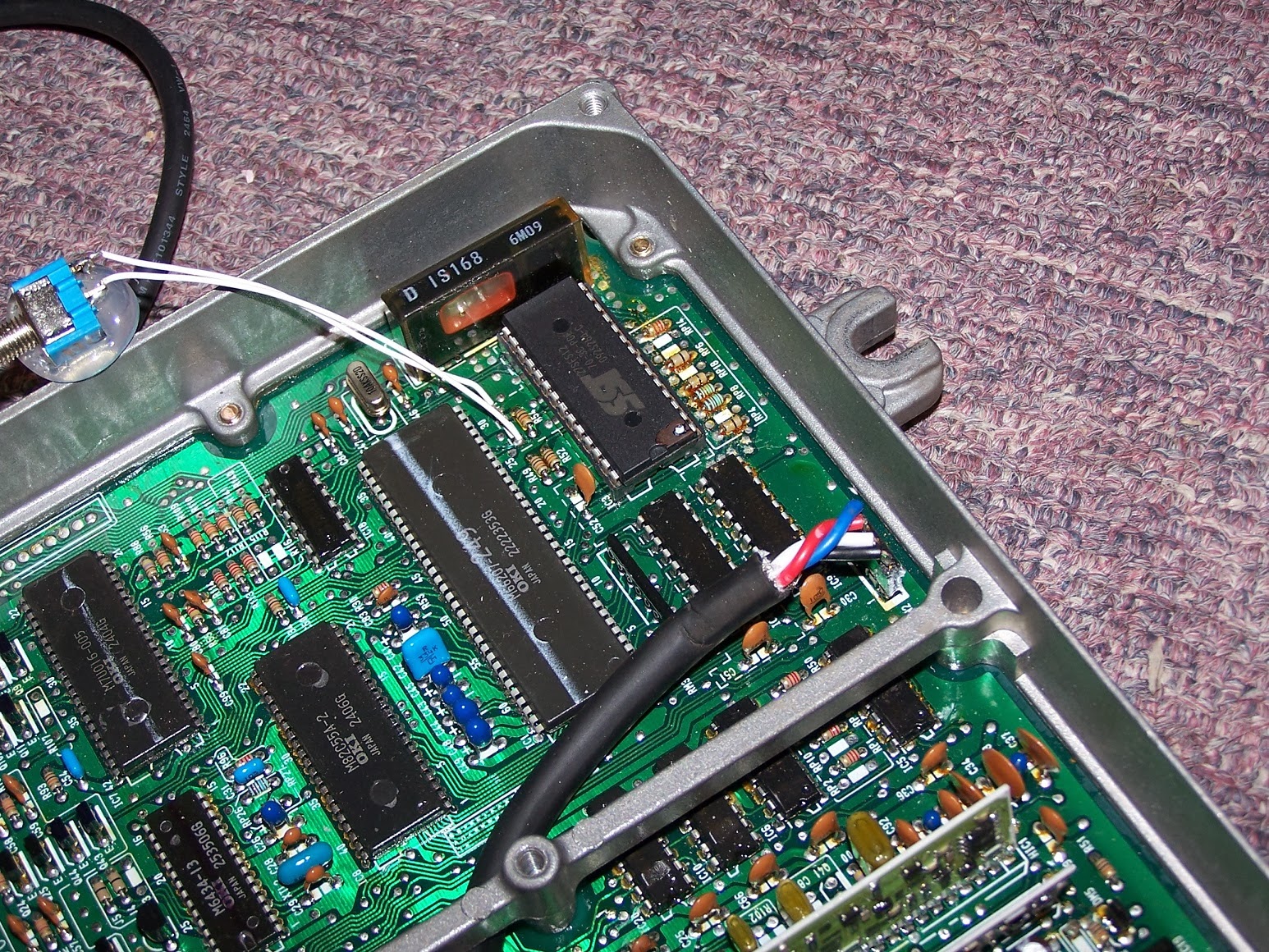
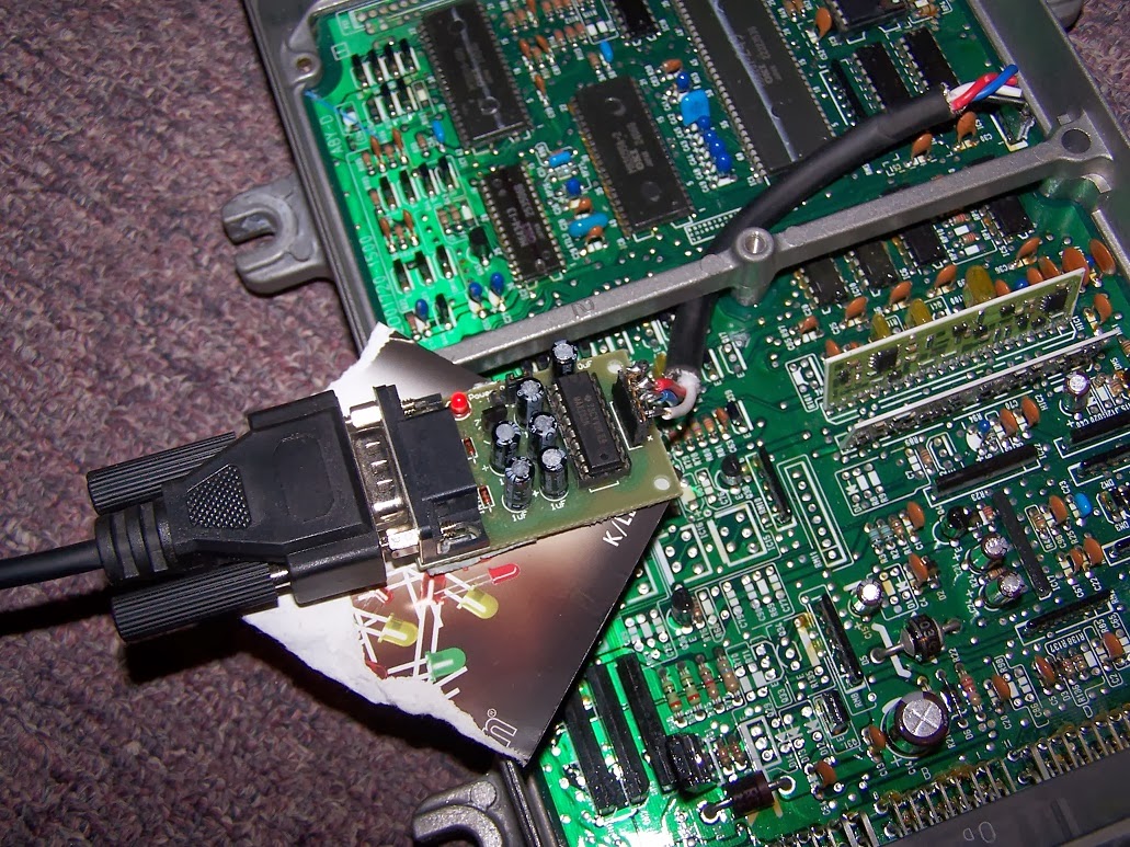
I started by getting a bench P06 to work, pull error codes, trigger ignition and injection events, make sure it was fully working on bench, then perform modifications so that the program could be replaced and add Datalogging to PC through RS232.
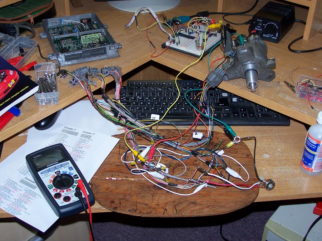
Bench ecu wiring and ecu


Please note the Chip marked SST at top of picture, this is where the new program resides
RS232 com device installed
Here is what looked like the adaptor to fit the D15 distributor on the 3S-GE. a rod to space the camshaft key( D15 camshaft key is suitable for the 3S-GE) a collar to center the D15 distributor on the 3S-GE head, and a plate to mount between head and distributor


 Software Side

I used the following software to make Binary files to burn on the EEPROM chips
Crome( Binary file editor for Honda ECUs, you make your tune in there)

I then used an EEPROM programmer SIMILAR BUT NOT EXACT to that one on ebay to burn on the chips my tune. installed the chip in it's socket on the PCB and power the ECU up

I used the following software to datalog what ECU sees at what particular time
FreeLog 1.0.87

If memory serves right I then used  maps from a B18 or B20 non VTEC engine with a D15 base program.

Testing on the engine

Test then began on the Test engine, please note that this ECU was tested on an engine not installed in a car so no real world testing was done. Only proof of concept that the ECU could be used correctly to start engine at all temperatures, that the engine could be revved without failures or bad behavior, that the ignition timing read with a timing light was the one in the tune.
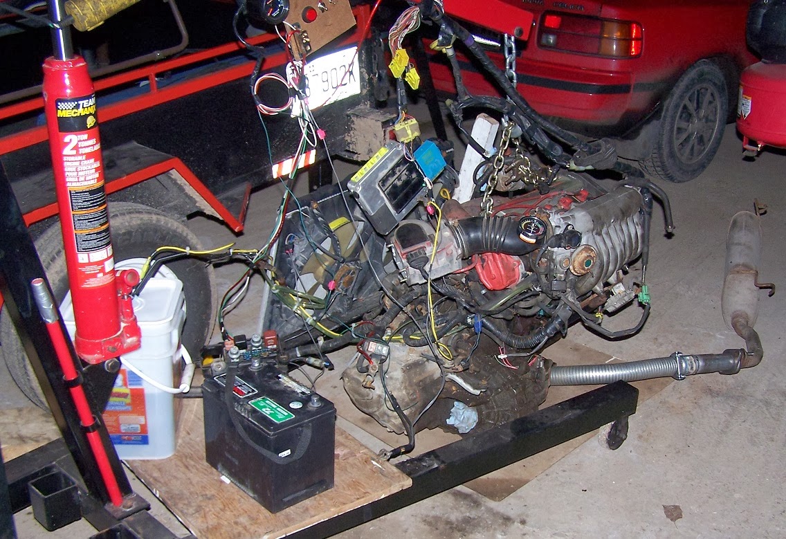
Test rig sporting 3S-GE electronics before test began, crude ;) but sufficient for the task

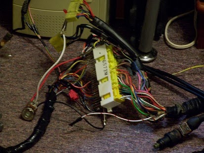
Close up of the connector receptacle used
As this turned out positive to that point, it was then time to make an adaptor to merge both mandatory Civic wiring and 3S-GE wiring. No files were kept to describe the exact correspondance of what signal went where, but If someone is interested we can make it up together easy and fast, it was not that complicated since both engine share electrical similitude (High impedance injectors and similar sensors pinout).
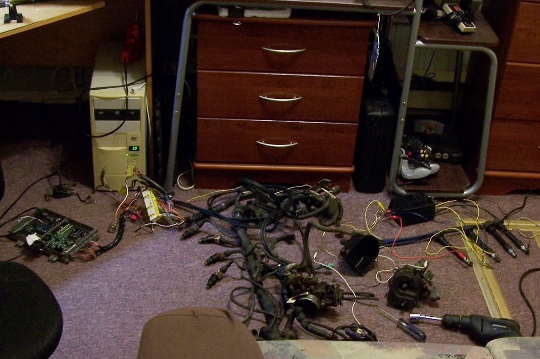
P06 ECU at left, adapter wiring in between , and ST162 3S-GE wiring at right
To work on a host engine using the P06 ecu  I used those Civic parts: Crank sensors, map sensor, and ignitor. Water and Air Temp sensors should probably used also but I used those of my 3S-GE at the time.
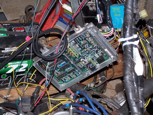
P06 ECU installed with Test engine


Distributor was installed in an orientation that made it suitable for the Pickup coils in the distributor to be in a good location in relation to TDC on 1st cylinder.
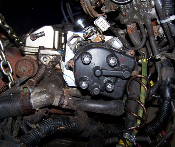
Do not take for granted the firing order written on the Cap, this is a bad lead!
As Honda engines of the time were counter clockwise rotating crankshaft, opposed to virtually every competitor being clockwise rotating crankshaft the Firing order on the Distributor had to be changed otherwise the engine could not be used. to do that simply invert spark plugs wires to the new correct order.(Please forgive me as that correct firing order was forgotten since then!)

I used B18 spark plug wires to connect to civic ECU and the 3S-GE head. the fitment was good enough on the 1st gen 3S-GE cylinder head.
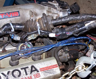
B18 spark plugs wires have the proper length and fitment

Map sensor signal was taken on the intake plenum.

After the correct firing order was found the engine ran great using this ECU. better idling than the 3S-GE ECU, better starting also, more agressive Ignition base maps used on Honda engines.

Here is the only video showing the 3S-GE being run by the P06,poor quality, does not show much, but here it goes!

What was accomplished at the time.

Recalibration was possible but this was a tedious process, you needed to burn a new chip every time you wanted to update your tune.
Datalogging was possible , which is not possible with a 1st gen 3S-GE ECU
1st gen 3S-GE without AFM, now using map sensor + IAT sensor and probably a more complex program than the 1986 3S ecu program.

In the end

In the end I started working with a Megasquirt-1+V3 PCB and fell in love with it, the P06 age ended for me and more flexible and complex EMS setup started to take form on the 3S-GE test mule and then on the 3S-GTE afterwards.

Further possibilities

-Using an EEPROM emulator like Moates ostrich would cut a lot of time in the process of building and testing the binary file, which at a point when the suitable file is made it is burned on a chip and used
-Using a P06 with a custom made crank sensor conditioner circuit, One could possibly use the stock toyota crank sensor and simplify by much the work involved and cleanliness of installation. this could also make this setup usable on many most toyota 4 cylinder engines of the same era. 

Monday, 27 January 2014

Program the flash memory on NXP LPC1769 (put a program on the LCP1769)

 INTRODUCTION

Using the Program Flash feature of LPCXpresso is the easiest way to get a program on an LPC1769 board, it does not require you to flash the board using a command line, it does not requires you to build that program in the IDE, it does not necessitate to start a debug sessing, with this method you can flash on a board a program that was written in an earlier version of the IDE without going through the assle of updating someone else code.
LPC1769 Board from Embedded Artists

 Some terminology used in this arcticle

  •  EA = E.mbedded A.rtists (this is the company that produce the board shown above, other versions are avaiblable too but this one is quite versatile and not too costly)
  •  NXP = NXP semiconductors, a company associated with Phillips that makes Microcontrollers
  •  IC = I.ntegrated C.ircuit ( this is a Silicon Chip that does a specific work, it might be a lot of things)
  • ADC = A.nalog D.igital C.onverter ( this is an device that reads analog voltages and convert it to digital data usable in processors)
  • PWM = P.ulse W.idth M.odulator (this device generate a frequency which On and OFF time vary)
  • IDE = I.ntegrated D.eveloppment E.nvironement (this is an application used to construct other applications)
  • MCU = Microcontroller (this is an IC that contains a processor, some RAM, some built in peripherals like ADC ,PWM ,Timers, Digital Inputs and Output), like an old computer with low power ,used to do tasks that require real time precision)
  • UI = U.ser I.nterface ( this is buttons, dialogs, windows, textboxes, pictures that compose an application)

What will you learn today

The aim of this article is to learn how to put a program on the LPC1769 board from EA with the use of a PC, USB cable and the Program Flash feature in LPCXpresso IDE.

REQUIERMENTS

This is all you need + PC, cleverness and patience!


  • PC with powerfull USB ports,(What??, yeah ... the EA boards require a USB port with good power to be able to flash the memory without errors. Avoid laptops if possible since they generally have weaker USB ports) 
  • PC with Windows XP SP3 or above, Windows 7 64b was used for the writing of this guide
  • USB cable with a Mini-B end
USB with Mini-B end 


 GETTING THE IDE TO WORK

The current version used for this guide is 6.1.4 using the default installation application UI layout

Get the Windows installer on NXP LPCXpresso download section 
Install the IDE following default choices, install the drivers when asked to.
Do not start the IDE at the completition of the installation.
Connect the LPC1769 board to USB cable to PC.
Let the computer install automatically the drivers for the device.
After this is done you can now start LPCXpresso

STARTING/SETUPING THE IDE FOR THE FIRST TIME

Check  'use this as the default and do not ask again', this will be simpler every time you start this application.

Application mandatory registration

Not registered warning
At first startup, the application will complain that it is not registered. To be able to program the LPC1769 flash memory we need to register .Please follow the steps below to do so, it should take you 5-10m playing in a web browser and copy/paste text data. It's boring, but in the end programming flash memory is a lot easier than not registering and building yourself the application and starting a debug session to get the program on the MCU ;)


1- You need to create a free user account on www.lpcware.com here

 2- once you have a working account, you can register an intstalled copy of LPCXpresso

Here are the steps to register in pictures, quite easy

get a serial number and start registration process
Get Activation key from lpcware.com using your user account and the serial number.
After this you have a registered free version of the IDE and you can use the Program Flash feature that was disabled before registration.

USING THE IDE TO INSTALL PROGRAM ON LPC1769


First you need a project built specifically for you target Board, in today's case this is a LPC1769 project.

You need to import your project in the IDE by using the following actions 

File/Import ...
Choose General/existing projects
Choose 'Select archive file' then find your ZIP file, check everything from your archive file then finish


Now that the project is imported in the Workspace you can install the  existing *.afx file on the LPC1769

Select your project in the Project Explorer
Then press on the Silicon Chip Icon , this is the Program Flash feature


LPCXpresso will initialize the LPC1769 board driver then display the Program Flash Dialog that will allow you at last to program the Board, the target board was detected by LPCXpresso and do not need to be changed

After you hit OK a progress dialog should appear and tell you if it succeeded or not. In case it did not succeed, think about using another USB port or even another computer, remember to avoid laptops for this task.
You have now finished with the IDE and therefore can close it

CONCLUSION

You now have a program on your LPC1769, everytime the board will be powered the program there will automatically start.