Introduction
Like the title means, let's go back in the past, the year is 2009 , A time when Engine management systems were a mystery to me. At that time I started the project to get a 3S-GTE to work without having the matching ecu and much everything in fact. Back then my skills in electronics were not much better than installing car stereos and simple analog electronic stuff, fog lights,repair broken wires,nothing to fancy. Please excuse the poor presentation of subjects in the pictures, having known I would have shared them It would have looked better!

As the avaricious young Lad I was, I decided to go with the cheapest alternative in exchange for more required skills to succeed. I found on the web that Honda civic ECUs were modifiable quite easily
and for cheap, I also found that they were successfully used on rare
occasions on the 3S-GTE which was my ultimate goal, but first I wanted
to make it work on a 3S-GE I had lying around, those engine
share a lot EMS wise and would be less of a loss if something went real bad with the tuning.
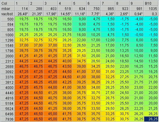 |
| example igniton map |
The leanring curve involved for a complete beginner was steep but I probably would do it the same way as the challenge was rewarding in the end. Please note that this document is a really rough tale of how to do this, 5 years have past since the events described here were made, so If you intend to do a similar project
where to learn to work with those ECUs go to pgmfi.org, this is where I learned everything about the P06 and most of the basics surrounding Engine management systems and the common strategies used to modify pre-OBD2 oem ECUs. Please do your research too and do not rely solely on what is written here. Any questions asked will be replied to the best of my knowledge tough . For details on
Mecanical and electronical aspect
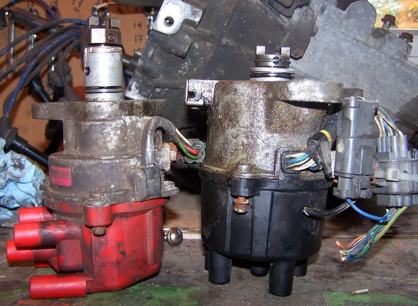 |
| 3S-GE left D15 right |
What was the biggest problem was that I neeeded to use the civic distributor( crank angle sensors are inside
) to match with the civic ecu. A friend of mine did the machining work to build an adaptor to bolt the distributor on the 3S-GE head and camshaft, Thanks Again Adam!.
The Honda P06 ecu was found in 1992-1995 d15 and d16 civic with already installed VTEC capabilities or not, was about 35-60 CDN$ available at most scrap yards.
Modifying cost were around 20-25 CDN$ in
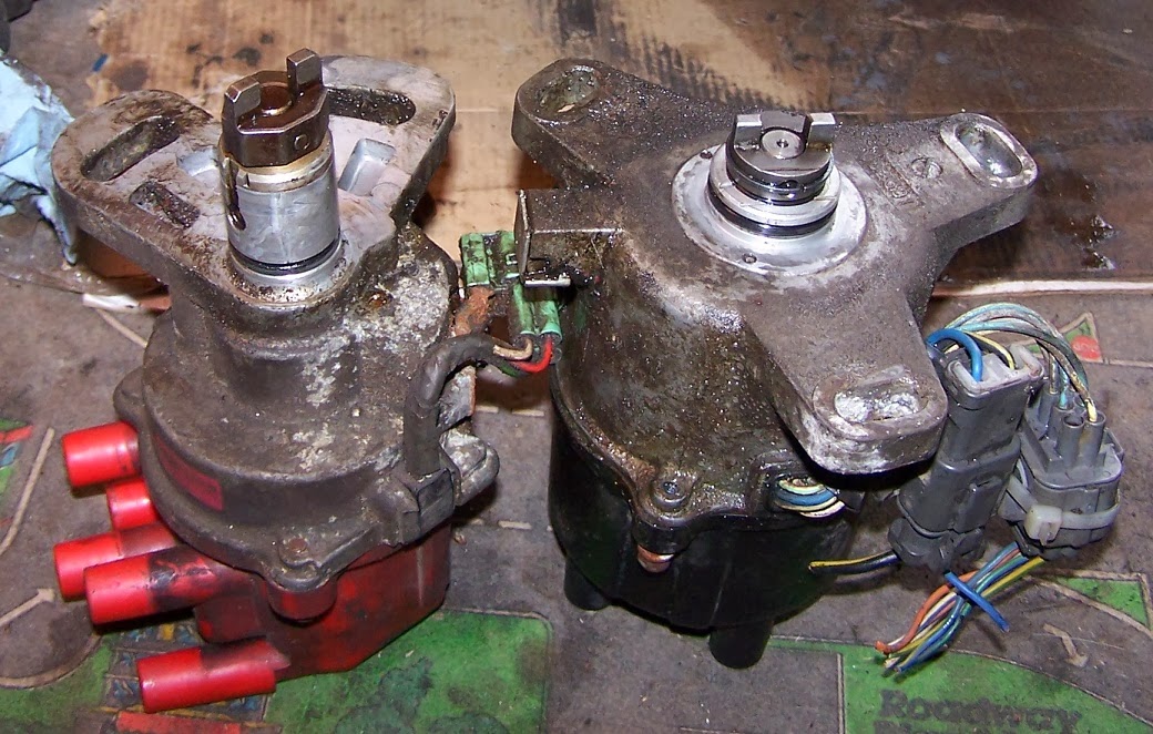 |
| 3S-GE left D15 right |
parts. It required soldering inside the ECU and have the tools to burn EEPROM chips when necessary.
So at that time I bought tools to burn chips and a stock of 27C256 compatible EEPROMs,mine were SST27SF512, as time goes by findind compatible EEPROM is getting harder.
I started by getting a bench P06 to work, pull error codes, trigger ignition and injection events, make sure it was fully working on bench, then perform modifications so that the program could be replaced and add Datalogging to PC through RS232.
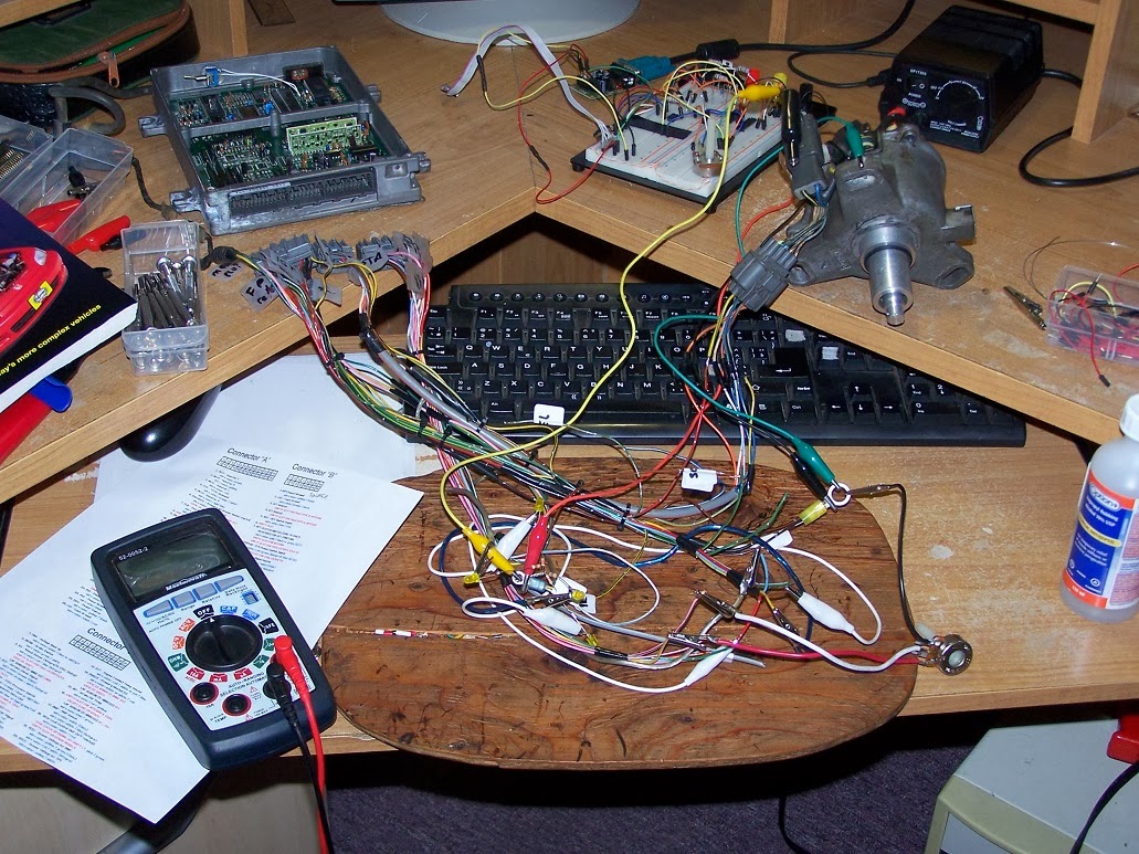 |
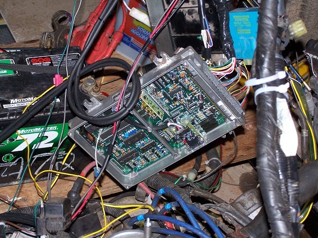
| Bench ecu wiring and ecu |
|
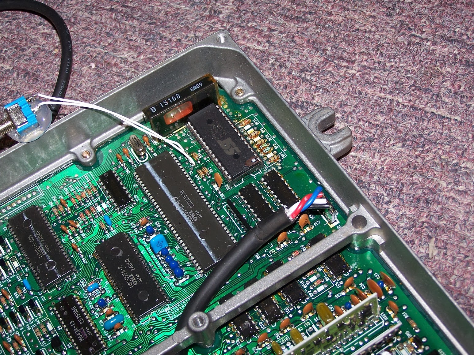 |
| Please note the Chip marked SST at top of picture, this is where the new program resides |
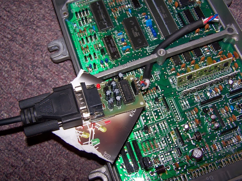 |
| RS232 com device installed |
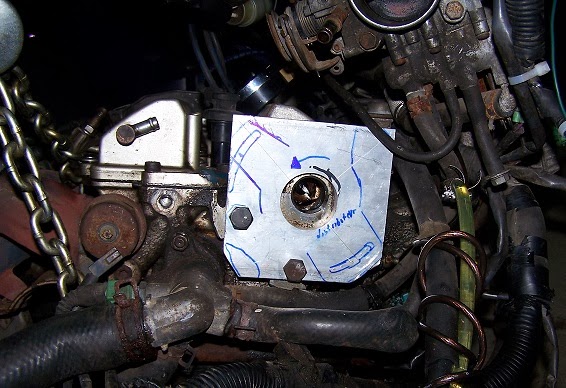
Here is what looked like the adaptor to fit the D15 distributor on the 3S-GE. a rod to space the camshaft key( D15 camshaft key is suitable for the 3S-GE) a collar to center the D15 distributor on the 3S-GE head, and a plate to mount between head and distributor

Software Side
I used the following software to make Binary files to burn on the EEPROM chips
Crome( Binary file editor for Honda ECUs, you make your tune in there)
I then used an EEPROM programmer SIMILAR BUT NOT EXACT to
that one on ebay to burn on the chips my tune. installed the chip in it's socket on the PCB and power the ECU up
I used the following software to datalog what ECU sees at what particular time
FreeLog 1.0.87
If memory serves right I then used maps from a B18 or B20 non VTEC engine with a D15 base program.
Testing on the engine
Test then began on the Test engine, please note that this ECU was tested
on an engine not installed in a car so no real world testing was done.
Only proof of concept that the ECU could be used correctly to start
engine at all temperatures, that the engine could be revved without
failures or bad behavior, that the ignition timing read with a timing
light was the one in the tune.
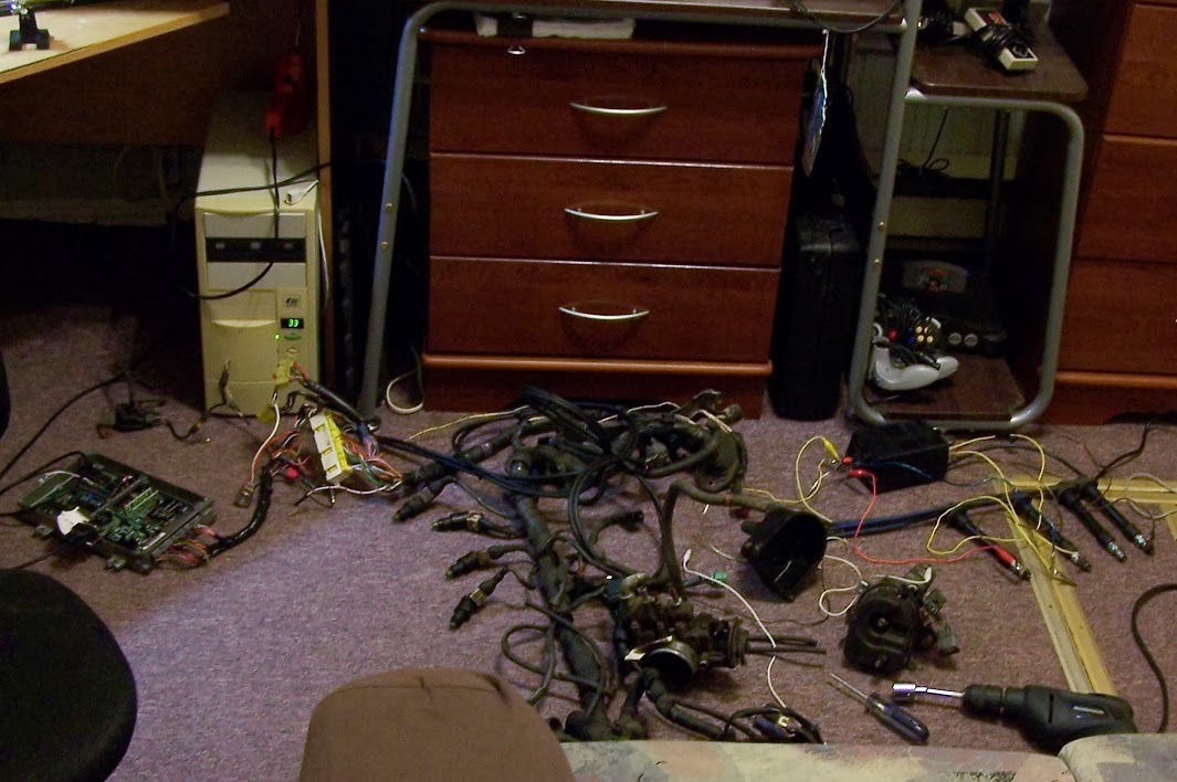
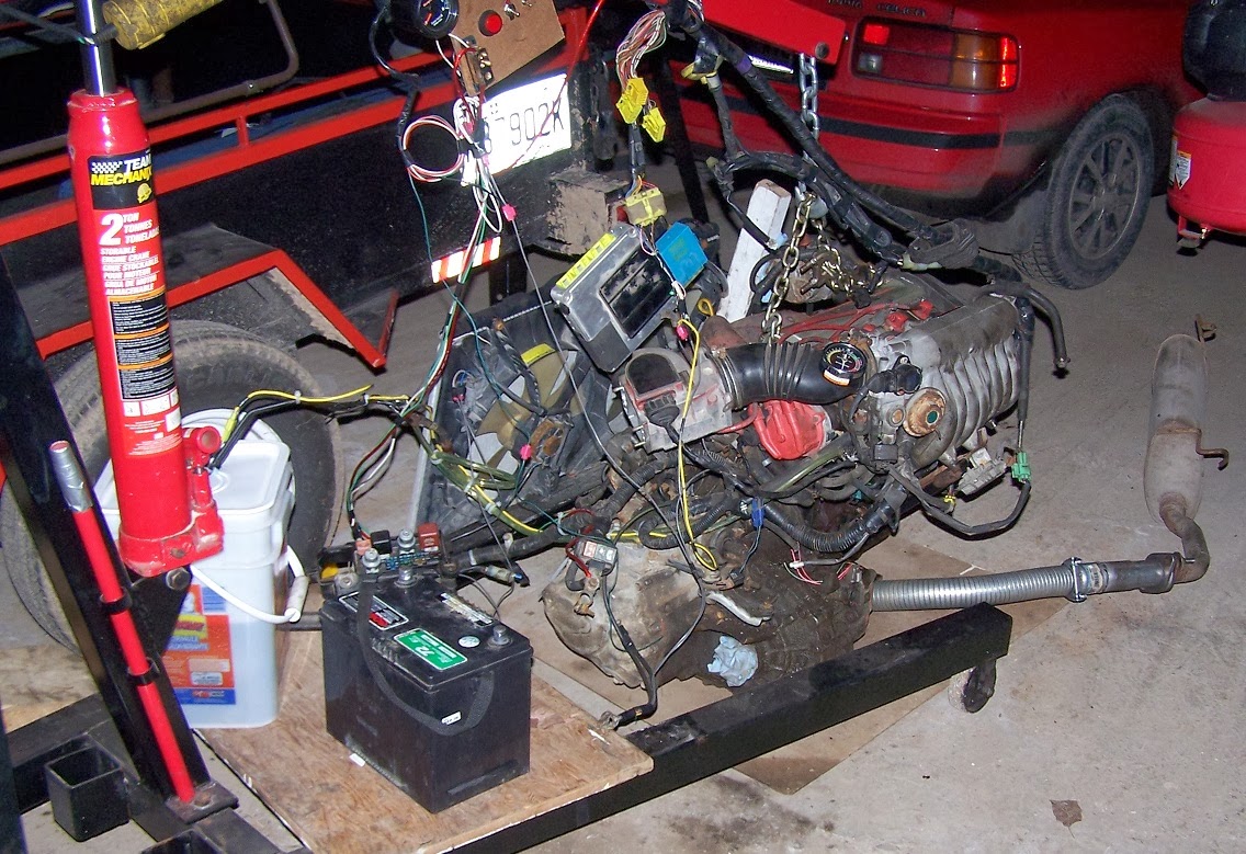 |
| Test rig sporting 3S-GE electronics before test began, crude ;) but sufficient for the task |
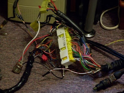 |
| Close up of the connector receptacle used |
As this turned out positive to that point, it was then time to make an adaptor to merge both mandatory Civic wiring and 3S-GE wiring. No files were kept to describe the exact correspondance of what signal went where, but If someone is interested we can make it up together easy and fast, it was not that complicated since both engine share electrical similitude (High impedance injectors and similar sensors pinout).
 |
| P06 ECU at left, adapter wiring in between , and ST162 3S-GE wiring at right |
To work on a host engine using the P06 ecu I used those Civic parts: Crank sensors, map sensor, and ignitor. Water and Air Temp sensors should probably used also but I used those of my 3S-GE at the time.
 |
| P06 ECU installed with Test engine |
Distributor was installed in an orientation that made it suitable for the Pickup coils in the distributor to be in a good location in relation to TDC on 1st cylinder.
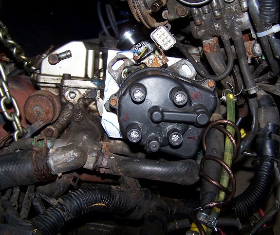 |
| Do not take for granted the firing order written on the Cap, this is a bad lead! |
As Honda engines of the time were counter clockwise rotating crankshaft,
opposed to virtually every competitor being clockwise rotating
crankshaft
the Firing order on the Distributor had to be changed otherwise the
engine could not be used. to do that simply invert spark plugs wires to the
new correct order.(Please forgive me as that correct firing order was forgotten since then!)
I used B18 spark plug wires to connect to civic ECU and the 3S-GE head. the fitment was good enough on the 1st gen 3S-GE cylinder head.
 |
| B18 spark plugs wires have the proper length and fitment |
Map sensor signal was taken on the intake plenum.
After the correct firing order was found the engine ran great using this ECU. better idling than the 3S-GE ECU, better starting also, more agressive Ignition base maps used on Honda engines.
Here is the only video showing the 3S-GE being run by the P06,poor quality, does not show much, but here it goes!
What was accomplished at the time.
Recalibration was possible but this was a tedious process, you needed to burn a new chip every time you wanted to update your tune.
Datalogging was possible , which is not possible with a 1st gen 3S-GE ECU
1st gen 3S-GE without AFM, now using map sensor + IAT sensor and probably a more complex program than the 1986 3S ecu program.
In the end
In the end I started working with a Megasquirt-1+V3 PCB and fell in love with it, the P06 age ended for me and more flexible and complex EMS setup started to take form on the 3S-GE test mule and then on the 3S-GTE afterwards.
Further possibilities
-Using an EEPROM emulator like
Moates ostrich would
cut a lot of time in the process of building and testing the binary
file, which at a point when the suitable file is made it is burned on a
chip and used
-Using a P06 with a custom made crank sensor conditioner circuit, One could possibly use the stock toyota crank sensor and simplify by much the work involved and cleanliness of installation. this could also make this setup usable on many most toyota 4 cylinder engines of the same era.


